please help!

opera936

New Member
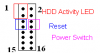
I recently replaced the motherboard on my compaq presario 7000 desktop, the replacement is the Intel D850GB Oocket 423 Pentium P4 Motherboard. i coulnd't find a way to powerup the board, when the powercable is plugged the light on the motherboard does get turn on, but using the compaq's original front panel cable connections doesn't work for the board. now i'm getting all frustrated bc i couldn't not power up this thing. lucky that compaq somewhat did name their cables. there r three cables colored green, black and yellow and they r tied together called power. the other four are blue, orange, red and white, under the group hd act. i found the "installation" manual on intel's site, but i just couldn't figure out how to do it. the installation for front panel is on pg66. ftp://download.intel.com/support/motherboards/desktop/d850gb/A2608002.pdf

any help would be greatly appreciated, thanx:cool:
 
You have to put the front power cable button into the pins that is specifies in the manual... :)
 
The manual should have a diagram and chart for pin locations. A small magnifying glass and flashlight to look over the block of pins on the board will suffice for locating the pairs of pins for the power and reset buttons alike. It is usually harder to get them actually plugged with a pair of tweezers then ir is to locate them on the block. On most boards the main block is at the edge of the board towards the front away from the pci slots or over near the connectors for the ide hard drvie(s) and cd/dvd drive(s).It's a small black colored block of short pins with pairs seen in different colored areas with a marking on the block itself like "psw", "reset", "pled", "hdled", etc..
 
Now to find that block of pins on the board click here and look for "P" <a href="<A href="http://imageshack.us"><img">http://imageshack.us"><img src="http://img262.imageshack.us/img262/8752/layoutcy5.jpg" border="0" alt="Image Hosted by ImageShack.us" /></a>

The front panel connections are seen at <a href="<A href="http://imageshack.us"><img">http://imageshack.us"><img src="http://img262.imageshack.us/img262/3745/frontpanelcn6.jpg" border="0" alt="Image Hosted by ImageShack.us" /></a>

The table #48 for those are at <a href="<A href="http://imageshack.us"><img">http://imageshack.us"><img src="http://img275.imageshack.us/img275/4112/table48rn0.jpg" border="0" alt="Image Hosted by ImageShack.us" /></a>
 
am i doing this rite?


tired both green and yellow on pin 6. the led for the hdd is colored red and white, and the led for the main power is blue and orange. thanx.
 
Yes, if you are actually hooking up the power switch to those 2 pins it's right. I read too fast though the first time, the power LED goes on the 3 pin header above the USB headers.
 

Attachments

  • untitled.PNG
    untitled.PNG
    2.5 KB · Views: 48
You have to look closely at the block itself to see just where those go on. A pocket sized magnifying glass is a useful tool there due to the small size of the block itself. There you can easily identify the markings for ech pair of wires. It's usually harder to get them on then find them since many boards have the block near the edge of the board next to the chassis.
 
Back
Top